I'll post a few personal projects here. You are welcome to study and use these designs as you wish. I only ask that you acknowledge the original authorship if you develop or share them further.
I provide no product support and make no claim that the designs are fit for any particular purpose. They are worth precisely what you paid for them! However, if you have any questions, please let me know and I'll do my best to answer.
The first of these designs is an indicator unit for classic cars. Pre-war and early post-war cars were not fitted with amber flashing indicators. Although the semaphore "trafficators" that were fitted are still legal in the UK, they are not what modern drivers expect to see. Flashing indicators are all but essential if you plan to use your car in today's traffic.
The sidelight "pod" that is usually fitted on the front wing is an excellent place to fit an amber indicator light, and conversion kits are available to squeeze two bulbs - an amber indicator and a white sidelight - into the space available. The drawback is that this requires an extra wire to be run to the front of the car to power the indicator bulb. On some cars this is relatively easy to fit. On others, it can represent several hours' work.
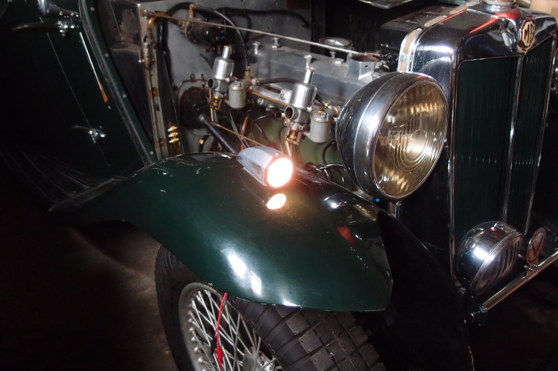
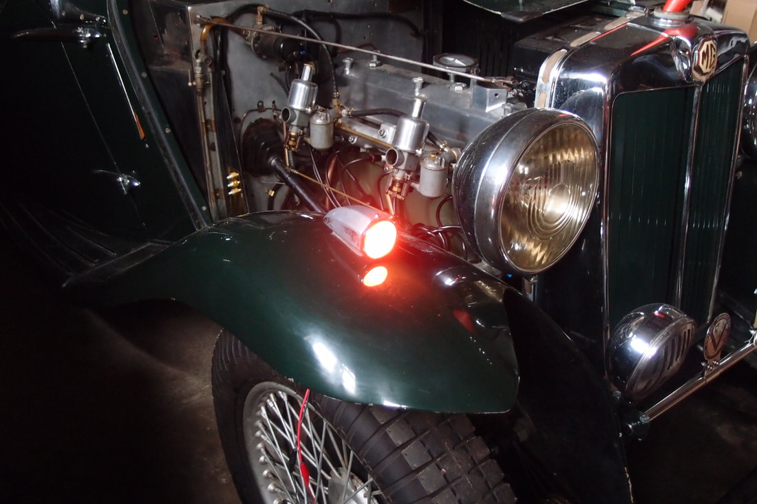
This design uses a high-power multi-colour LED that will glow either white or amber depending on the voltage applied. If it is fed 6v, it will glow a relatively soft white, similar to the original 5W sidelight. If it is given 12v, it will produce a much brighter amber, similar to a 21W amber bulb.
All cars are electrically noisy and difficult environments in which to work. You cannot rely on the nominal 6v fed down a wire to the indicator unit actually being 6v when it is received at the far end, nor can you rely on a nominal 12v actually being a reliable, steady 12v. Because of this the indicator unit incorporates some hysteresis. The colour goes from white to amber when the voltage applied exceeds 10v, but it goes back to white when it falls below 8v.
The indicator uses a high-output RGB LED. I used a Lumex SML-LX1610RGBW/A, although others are available. Other designers have successfully used arrays of smaller LEDs, rather than one high-power one. Each colour element of the LED is rapidly turned on and off. The duty cycle - how long on versus how long off - controls the intensity of each element.
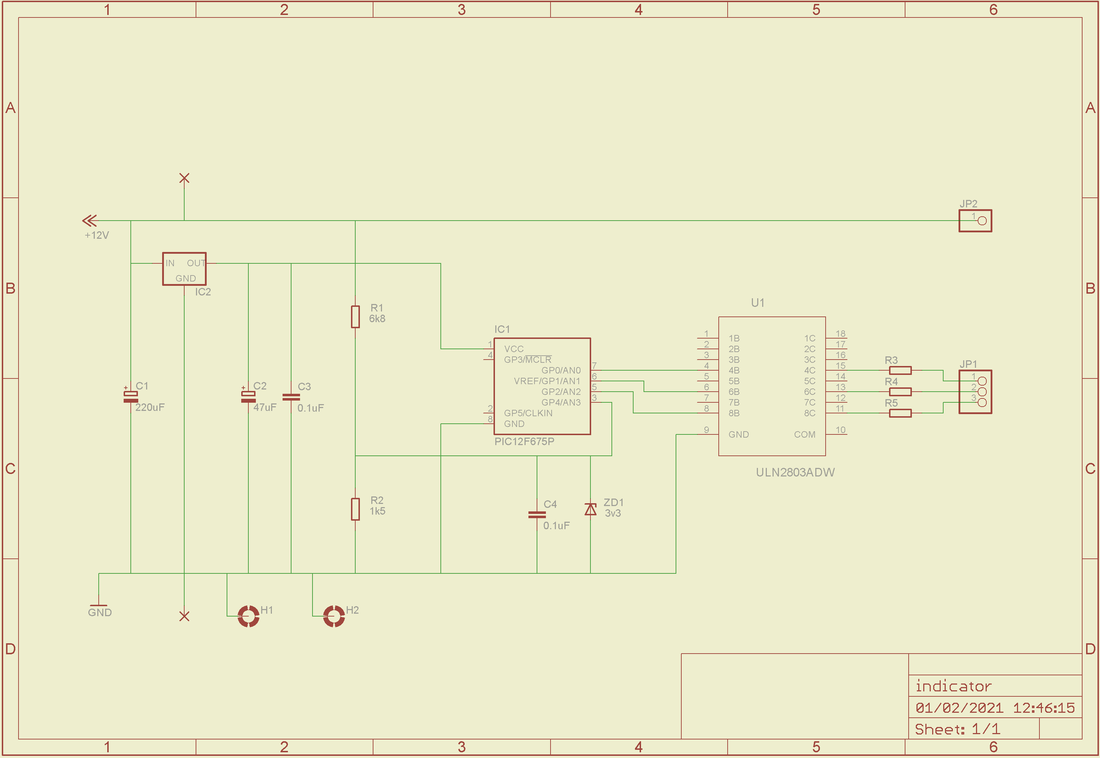
The schematic is shown below:
The voltage regulator IC2 and capacitors C1 and C2 provide a stable 3.3v supply to IC1, regardless of the supply voltage. IC1 is a Microchip PIC12F675 microcontroller. For anyone brought up on home computers in the 80s, these chips are a dream. They have roughly comparable computing power to the Z80s and 6502s that we programmed back then, but they have program and data memory, an oscillator, and various peripherals built in. This one includes an analogue to digital converter and, of its eight pins, six can be used as I/O ports. I use three pins as outputs for the three primary colours, and one (pin 3) as an analogue input to measure the voltage on the supply line, via a potential divider formed by R1 and R2. Other products in the PIC range include peripherals such as USARTs (used in our MIDI designs), USB interfaces (used in the Amethyst ignition unit) and Ethernet interfaces (used in Mains Monitor).
U1 is an 8-output Darlington driver array, of which I use only three outputs. This is needed because the PIC cannot sink enough current to drive the LED directly. It might have been more sensible to use three discrete transistors, but I had some ULN2803's in stock, so I decided to use one of those on the prototype. But then I needed to use the surface mount version of the ULN2803 in order to save space on the board, but I didn't have any of those, so I had to order anyway!
R3 and R4, for red and green, are 33 ohm 3W resistors. The blue bulb is less heavily used than the others - it is not used at all in our amber light, and none of the bulbs is lit very brightly for the white light - so we use an 82 ohm 1W resistor there. If you wanted to produce other colours apart from amber and the relatively dull white, it would be sensible to use a 33 ohm 3W resistor for blue as well as red and green
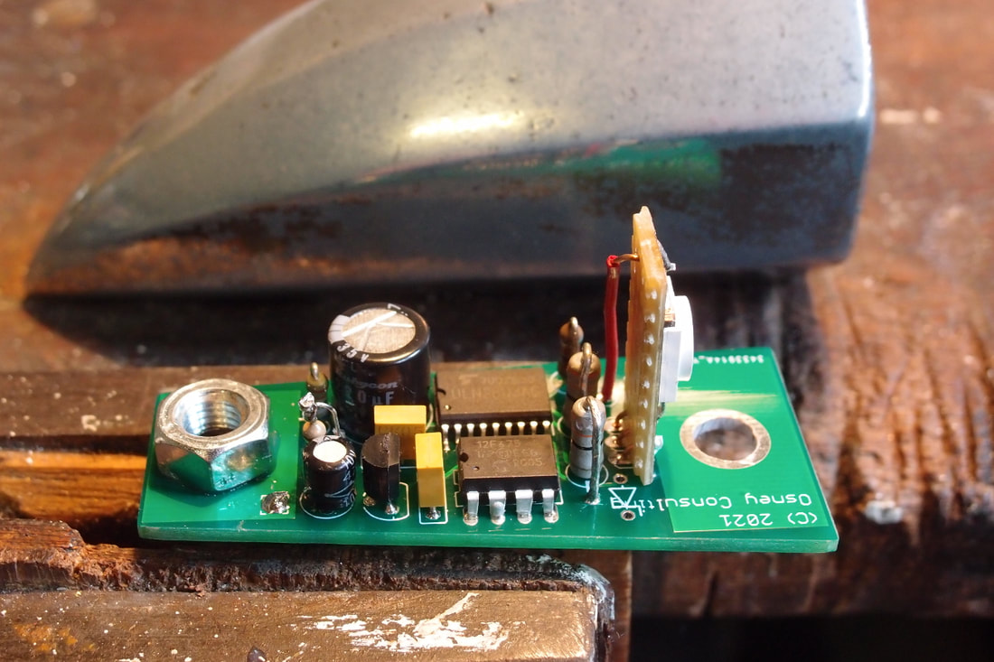
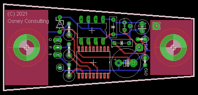
The PCB design is shown below. The Gerbers can be downloaded from here. As you can see in the photo above, I have mounted the LED on a tiny piece of Veroboard, although it would look more professional with a little daughter PCB. The parts list is here.
The board is 66mm long and 30mm wide at its widest point, and fits neatly inside the indicator unit. The two mounting holes are 2" apart and the power cable enters the board directly above a third hole on a standard "torpedo" indicator. The unit can safely be mounted on two plastic spacers, each a few millimetres long.
The software for the microcontroller is written in C and can be downloaded from here. This is compiled into a hex file, which is programmed into the chip using a PIC programmer. The compiled hex file is here.
The colour definitions aren't hard-coded into the program. They are stored in the microcontroller's data EEPROM and need to be programmed in (with the PIC programmer) separately. The bulbs are lit according to an 18-step cycle, and the numbers for each colour specify for how many 18th of the time the bulb will be lit. I use the following definitions, but you can use different colours if you prefer:
EEPROM byte 0: White light, red bulb 12
EEPROM byte 1: White light, green bulb 18
EEPROM byte 2: White light, blue bulb 8
EEPROM byte 3: Amber light, red bulb 18
EEPROM byte 4: Amber light, green bulb 16
EEPROM byte 5: Amber light, blue bulb 0
Lastly, if the car is going to be used in a hostile environment - cold, damp, or rained on - then I'd recommend that a conformal coating be used to protect the components once the PIC is programmed and the board assembled.
